15
LTC4210-1/LTC4210-2
421012f
Normal Mode/External Timer Control
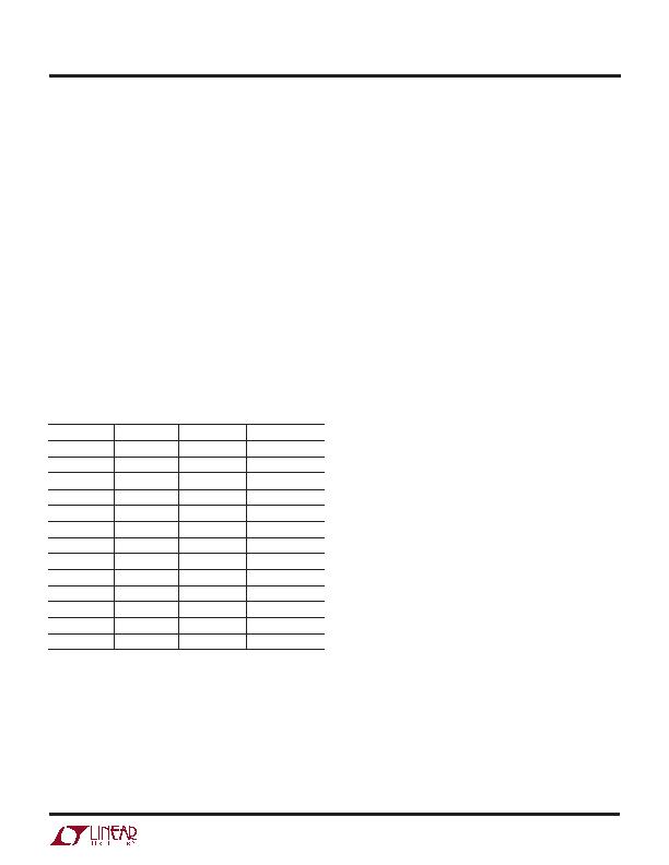
Whenever the TIMER pin voltage drops below the COMP1
threshold, but is not in reset mode, the TIMER enters
normal (100礎 source) mode with an equivalent 7k resis-
tive pull-down. Table 1 shows the relationship of t
INITIAL
,
t
CBDELAY
, t
COOLOFF
vs C
TIMER
.
If the TIMER pin is pulled beyond the COMP2 threshold,
the GATE pin is pulled to ground immediately. This allows
the TIMER pin to be used for overvoltage detection, see
Figure 11.
Externally forcing the TIMER pin below the COMP1 thresh-
old will reset the TIMER to normal mode. During overvolt-
age detection, the TIMERs 100礎 pull-down current will
continue to be on if (V
CC
SENSE) voltage is below 50mV.
If the (V
CC
SENSE) voltage exceeds 50mV during the
overvoltage detection, the TIMER current will be the same
as described for latched-off or autoretry mode. See the
section OVERVOLTAGE DETECTION USING TIMER PIN
for details of the application.
Power-Off Cycle
The system can be reset by toggling the ON pin low for
more than 30祍 as shown at time point 7 of Figure 3. The
GATE pin is pulled to ground. The TIMER capacitor is also
discharged to ground. C
LOAD
discharges through the load.
Alternatively, the TIMER pin can be externally driven above
the COMP2 threshold to turn off the GATE pin.
POWER MOSFET SELECTION
Power MOSFETs can be classified by R
DSON
at V
GS
gate
drive ratings of 10V, 4.5V, 2.5V and 1.8V. Use the typical
curves VGATE vs Supply Voltage and VGATE vs Tem-
perature to determine whether the gate drive voltage is
adequate for the selected MOSFET at the operating volt-
age.
In addition, the selected MOSFET should fulfill two V
GS
criteria:
1. Positive V
GS
absolute maximum rating > LTC4210
maximum V
GATE
, and
2. Negative V
GS
absolute maximum rating > supply
voltage. The gate of the MOSFET can discharge faster
than V
OUT
when shutting down the MOSFET with a large
C
LOAD
.
If one of the conditions cannot be met, an external Zener
clamp shown on Figure 10a or Figure 10b can be used. The
selection of R
G
should be within the allowed LTC4210
package dissipation when discharging V
OUT
via the Zener
clamp.
APPLICATIO S I FOR ATIO
U
U
U
Table 1. t
INITIAL
, t
CBDELAY
, t
COOLOFF
vs C
TIMER
C
TIMER
(?/SPAN>F)
t
INITIAL
(ms)
t
CBDELAY
(ms)
t
COOLOFF
(ms)
0.033
9.0
0.7
18.2
0.047
12.8
1
25.9
0.068
18.6
1.5
37.4
0.082
22.4
1.8
45.1
0.1
27.3
2.2
55
0.22
60.0
4.8
121
0.33
90.1
7.2
181.5
0.47
128.3
10.2
258.5
0.68
185.6
14.7
374
0.82
223.8
17.8
451
1
272.9
21.7
550
2.2
600.5
47.7
1210
3.3
900.7
71.5
1815
发布紧急采购,3分钟左右您将得到回复。
相关PDF资料
LTC4211IMS8
IC CONTROLLER HOT SWAP 8-MSOP
LTC4212IMS#TRPBF
IC CTRLR HOTSWAP TIMEOUT 10MSOP
LTC4214-1IMS#TRPBF
IC CTRLR HOTSWAP NEGVOLT 10MSOP
LTC4215IUFD#PBF
IC CNTRLR HOT SWAP 24-QFN
LTC4216IDE#TRPBF
IC CNTRLR HOT SWAP 12-DFN
LTC4221IGN#TRPBF
IC CTRLR HOTSWAP DUAL 16SSOP
LTC4222CG#PBF
IC CTRLR DUAL HOT SWAP 36-SSOP
LTC4223CDHD-2#PBF
IC CNTRLR HOT SWAP DUAL 16-DFN
相关代理商/技术参数
LTC4210-2CS6#TRMPBF
功能描述:IC CONTROLLER HOT SWAP TSOT23-6 RoHS:是 类别:集成电路 (IC) >> PMIC - 热交换 系列:- 标准包装:50 系列:- 类型:热交换控制器 应用:-48V 远程电力系统,AdvancedTCA ? 系统,高可用性 内部开关:无 电流限制:可调 电源电压:11.5 V ~ 14.5 V 工作温度:-40°C ~ 85°C 安装类型:表面贴装 封装/外壳:10-TFSOP,10-MSOP(0.118",3.00mm 宽) 供应商设备封装:10-MSOP 包装:管件
LTC4210-2CS6#TRPBF
功能描述:IC CONTROLLER HOT SWAP TSOT23-6 RoHS:是 类别:集成电路 (IC) >> PMIC - 热交换 系列:- 标准包装:50 系列:- 类型:热交换控制器 应用:-48V 远程电力系统,AdvancedTCA ? 系统,高可用性 内部开关:无 电流限制:可调 电源电压:11.5 V ~ 14.5 V 工作温度:-40°C ~ 85°C 安装类型:表面贴装 封装/外壳:10-TFSOP,10-MSOP(0.118",3.00mm 宽) 供应商设备封装:10-MSOP 包装:管件
LTC4210-2IS6
制造商:LINER 制造商全称:Linear Technology 功能描述:Hot Swap Controller in 6-Lead SOT-23 Package
LTC4210-2IS6#PBF
制造商:Linear Technology 功能描述:HOT SWAP CNTRL INT SWITCH 6T 制造商:Linear Technology 功能描述:HOT SWAP CNTRL, INT SWITCH, 6TSOT23 制造商:Linear Technology 功能描述:HOT SWAP CONTROLLER, 2.7-16.5V, TSOT-23-6; Controller Applications:Electronic Circuit Breaker, Hot Board Insertion, Industrial High Side Switch / Circuit Breaker; Internal Switch:Yes; Supply Voltage Min:2.7V; Supply Voltage Max:16.5V;RoHS Compliant: Yes
LTC4210-2IS6#TR
功能描述:IC CONTROLLER HOT SWAP TSOT23-6 RoHS:否 类别:集成电路 (IC) >> PMIC - 热交换 系列:- 标准包装:50 系列:- 类型:热交换控制器 应用:-48V 远程电力系统,AdvancedTCA ? 系统,高可用性 内部开关:无 电流限制:可调 电源电压:11.5 V ~ 14.5 V 工作温度:-40°C ~ 85°C 安装类型:表面贴装 封装/外壳:10-TFSOP,10-MSOP(0.118",3.00mm 宽) 供应商设备封装:10-MSOP 包装:管件
LTC4210-2IS6#TRM
制造商:Linear Technology 功能描述:Hot Swap Controller 1-CH 16.5V 6-Pin TSOT-23 T/R
LTC4210-2IS6#TRMPBF
功能描述:IC CONTROLLER HOT SWAP TSOT23-6 RoHS:是 类别:集成电路 (IC) >> PMIC - 热交换 系列:- 标准包装:50 系列:- 类型:热交换控制器 应用:-48V 远程电力系统,AdvancedTCA ? 系统,高可用性 内部开关:无 电流限制:可调 电源电压:11.5 V ~ 14.5 V 工作温度:-40°C ~ 85°C 安装类型:表面贴装 封装/外壳:10-TFSOP,10-MSOP(0.118",3.00mm 宽) 供应商设备封装:10-MSOP 包装:管件
LTC4210-2IS6#TRPBF
功能描述:IC CONTROLLER HOT SWAP TSOT23-6 RoHS:是 类别:集成电路 (IC) >> PMIC - 热交换 系列:- 标准包装:50 系列:- 类型:热交换控制器 应用:-48V 远程电力系统,AdvancedTCA ? 系统,高可用性 内部开关:无 电流限制:可调 电源电压:11.5 V ~ 14.5 V 工作温度:-40°C ~ 85°C 安装类型:表面贴装 封装/外壳:10-TFSOP,10-MSOP(0.118",3.00mm 宽) 供应商设备封装:10-MSOP 包装:管件
